How to build a custom Binary CLK with the DS3231, deployed on an ATtiny4313
Designed by:
Colin "MrSwirlyEyes" Keef
The Binary CLK (BCLK) is fun application of system on a chip design. (Also, an application of the ATTiny Programmer!). We will be programming an AVR microcontroller, namely the ATTiny4313, to light up 13 LEDs in such a way that we can display the hours and minutes, in the format HH:MM, as a 24H BCD (Binary Coded Decimal) clock.
We will be able to use the Arduino IDE to do our programming, and then we can simply upload our program to the ATTiny4313 using traditional methods (or, optionally, an ATTiny Programmer).
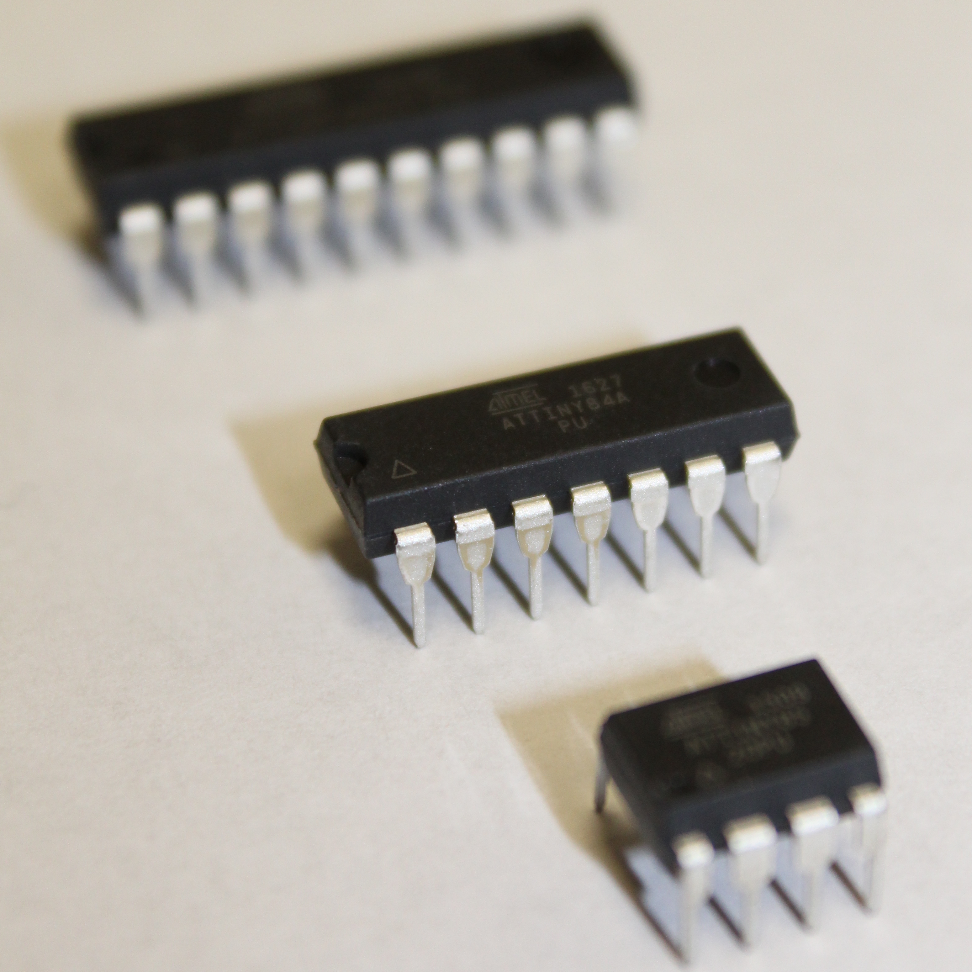
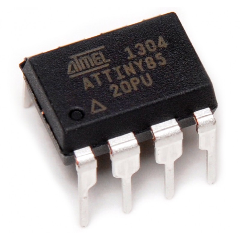
The ATTiny4313 is amongst a class of cheap 8-bit microcontrollers (MCU). ATTinys are like the ATMEGA328P, the heart of the Arduino UNO. They are of the same class, family, and manufacturer – the ATMEL (now Microchip) microcontroller family. We chose the ATTiny4313 because the number of GPIO pins available was convenient for the size of the package.
The BCLK will utilize a RTC (Real Time Clock) to fetch time. The RTC we will use is the DS3231. We will program the RTC DS3231 with current time, and it will keep track of the time on its own. It has a coin cell battery that will consume very little power to keep track of time while our BCLK is off. The DS3231 is extremely accurate, even several months from after you program it, it will be accurate within a few seconds – not bad for the price.
The process of communicating between the RTC DS3231 using I2C is beyond the scope of our project. Thus, we will be providing you with our code and library to program the RTC. Furthermore, you will program the logic to take the (given) time from the DS3231 in (decimal) hours and minutes, and convert it to the BCD displayed on the BCLK.
Finally, this project incorporates a challenging PCB (Printed Circuit Board) design component, so that the final BCLK design is modular (that is, two individual PCB boards that are interconnected), and acts as its own stand. You will have to align the pins together perfectly to get a clean and awesome board.
This project incorporates several components: programming an ATTiny MCU, programming the RTC DS3231, programming the BCLK logic, two PCB boards to design, and soldering. However, the result is a fun, classic circuit that is a worthwhile learning experience!
| DEVICE | VENDOR URL | QUANTITY | NOTES |
|---|---|---|---|
| ATTINY4313 8BIT 4KB FLASH 20DIP | Digikey | 1 | May substitute for any other ATtinyX313 module. |
| CONN IC DIP SOCKET 20POS TIN | Digikey | 1 | |
| VOLTAGE REG IC LINEAR 5V 300MA SOT23-5 | Digikey | 1 | |
| CAP CER 0.1UF 50V 0805 | Digikey | 6 | |
| CAP CER 10UF 35V 0805 | Digikey | 2 | |
| SWITCH SLIDE SPDT 300MA 4V | Digikey | 1 | |
| RES 10K OHM 1/4W 5% AXIAL | Digikey | 13 | Can substitute for appropriate sized resistor(s). |
| DS3231 Real Time Clock Breakout Module | Amazon | 1 | |
| (1x06) CONN HEADER FEMALE 6POS .100" TIN | Digikey | 1 | |
| BATTERY ALKALINE 9V | Digikey | 1 | |
| BATTERY CONNECT SNAP 9V 4" LEADS | Digikey | 1 | |
| (1x14) CONN HEADER R/A 14POS 2.54MM | Digikey | 1 | |
| Binary CLK PCB Control Module | OSH Park | 1 | Latest revision. |
In this module, we will prototype an LED array. This will essentially be the Binary CLK, just not in clock form (yet), no DS3231 real-time clock (yet) and using the Arduino UNO. This is to demonstrate that using the Arduino UNO is a valid method for prototyping. The Arduino UNO is a development board which has the benefits of being easy to use, and the convenient package that the Arduino UNO comes in (i.e. with the labeled header pin arrays). Then we will port over to the appropriate microcontroller for the particular application. In this case, we will be using the ATtiny4313. The ATtiny4313 is not as convenient as the Arduino UNO; it is simply a microcontroller IC (integrated circuit) package, and not a development board. It does not have the convenient header pins and labels.
Thus, we will construct a four columns of LEDs on a breadboard (resembling the form of our Binary CLK, and then write a simple program the light up the LEDs using the Arduino UNO. While you work, keep in mind that we will port this over to an ATtiny4313 soon and for the final part - the Binary CLK.
We will start off easy with a simple example of toggling an LED ON and OFF.
Construct the following circuit to connect the Arduino UNO to a single LED:
Programming the LED is about as simple as the circuit. The following is the typical blink sketch that is commonly used as the "Hello World" of hardware:
To run the code. Be sure to select:
Then click on the Upload button (or press CTRL/CMD + U) to upload the code to the Arduino UNO.
The behavior should be as follows:
An LED toggling ON and OFF every 500ms (0.5s). Easy right? Now lets build atop this!
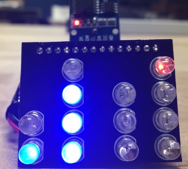
In this challenge, we want to prototype our Binary CLK using the Arduino UNO. We will have 13 LEDs on our Binary CLK, so we need to expand our single LED example to 13. Further more, we want to emulate how our Binary CLK will look as well. We encourage trying to make 4 columns for the Binary CLK with the appropriate number of LEDs to mimick our forthcoming Binary CLK.
Construct a circuit to program 13 LEDs (with the appropriate corresponding resistors) using the Arduino UNO. You may use any valid pins you want.
You may program any behavior you want. (You do NOT have to code for the expected behavior for the Binary CLK yet). We will demonstrate the same behavior as the single LED extended to the array of 13 LEDs. Here is an example of our challenge solution:
Any LED behavior is acceptable, as long as all the LEDs demonstrate functionality.
Keep in mind, you will have the opportunity to program a beautiful lightshow later!
If you are using the Arduino IDE's Serial Monitor, then the LED on pin 0 and 1 may behave wonky when writing to it. Pin 0 (RX) and pin 1 (TX) are shared with the Serial Monitor (e.g. when you use Serial.print(...)) so any device (e.g. LED) may receive a HIGH or LOW signal even if you are explicitly writing a particular value to it (or not).
Note that this solution is NOT the only solution. This is just how we realized it. It should look almost exactly the same as the code we started with when testing the single LED. The only difference is the addition of several more LEDs. We also employed an array for its ease, convenience, and code readibilty.
The schematic should be similar to the following:
Again, the code can vary, but here is what we have for our solution:
Hopefully this challenge was not too difficult, this was meant to be very simple - after all, we just started. The value in this project is to demonstrate the transition from prototyping to product!
In this module, we explore the DS3231 real-time clock (RTC). We will program the RTC so that our Binary CLK can keep track of time even when it is off so that anytime the Binary CLK is turned on, we are able to have our highly accurate time without reprogramming it.
text
To learn about the DS3231 RTC in general we direct you to our DS3231 Real-Time Clock tutorial. You will need to follow the all of the modules which will introduce you to the RTC, installing the necessary library to communicate with the DS3231, and then programming the DS3231 itself.
Now that you have your DS3231 programmed, we are ready to program the Binary CLK logic.
In this challenge, we will explicitly program the DS3231. Follow the DS3231 Real-Time Clock tutorial closely and program the DS3231 with the current date and time.
Here is the behavior of the challenge printing the DS3231 time after programming it alongside with the date and time displayed in the top-right corner:
Note that this solution is NOT the only solution. This is just how we realized it.
The schematic should be similar to the following:
Here are the results I got after a few uploads and was happy with the approximate 1 second of delay:
If you want to keep this time, be sure the coin-cell battery is inserted into the DS3231 breakout module.
After you are happy with your programmed time. Turn off the Arduino or remove the connection to the DS3231. If you restart the Arduino (or the Serial Monitor), it will reprogram the DS3231 at the compile time from when you uploaded it. If you want to see the time without programming it again, you will need to remove the line of code that sets the time on the DS3231 and reupload the code again.
In this module, we will program the Binary CLK logic. We have already programmed the DS3231 RTC and get extract the time. Next is to program the Arduino UNO appropriately, such that we: retrieve the current time from the RTC, then write to the appropriate LEDs that displays the current time in BCD (Binary Coded Decimal).
Although our RTC can give us the the date and time, we are only interested in the time. Specifically we only need the hour and minute, this is all our Binary CLK can support.
When we receive the time from the RTC we obtain the time as an int (technically we receive a byte, but you can use either interchangeably). Given the hour and minute, we need to map these int values to the appropriate LEDs to represent the time.
Our Binary CLK is designed as follows:
Remember, our Binary CLK will represent 24H time. (So we do not need an AM/PM indicator).
There are four columns on our Binary CLK. The two left-most columns represent the hour. The two right-most columns represent the minute.
Since in decimal the time can be represented with up to two digits (e.g. 59 minutes - the 5 is the most significant minute, and 9 is the least significant minute, or 23 hours - the 2 is the most significant hour, and 3 is the least significant minute), we represent each of the two columns for hour and minute with a column that represents the most significant digit (MSD) and the least significant digit (LSD).
There are also four rows on our Binary CLK. The bottom row represents a weight of 1. The next row, a weight of 2. The next row, a weight of 4. The top row, a weight of 8.
So, for example, to represent the time: 23:59 (11:59 PM). The hour is 23, the minute is 59:
When you program your Binary CLK it is not wise to program for every possible case. There are also several different ways to program the Binary CLK that range from straight-forward and simple to complex and clever.
We believe a straight-forward way of programming the Binary CLK is to program for each column. The hour ranges from 00 - 23. The H_MSD column ranges from 0 - 2. The H_LSD column ranges from 0 - 9. The minute ranges from 00 - 59. The M_MSD column ranges from 0 - 5. The M_LSD column ranges from 0 - 9.
We represent this through the following block diagram. This can essentially be your main loop:
Although we have drawn the block diagram in parallel - we cannot perform parallel computation on an AVR microcontroller. But logically we can think of the hour and minute separately - hence the parallelism.
We can think of the digits of time for each column (H_MSD, H_LSD, M_MSD, M_LSD) individually. For example, think of all the cases for the H_MSD being a 0, that is 0X:XX (e.g. 00:XX, 01:XX, ..., 08:XX,and 09:XX), where we do not care what X is. And we write the H_MSD_1 LED and H_MSD_2 LED off. Similarly, for the H_MSD being a 1, that is 1X:XX (e.g. 10:XX, 11:XX, ..., 18:XX, and 19:XX). And we write the H_MSD_1 LED on, and H_MSD_2 LED off. Similarly, for H_MSD being a 2, that is 2X:XX (e.g. 20:XX, 21:XX, 22:XX, and 23:XX). And we write the H_MSD_2 LED on, and the H_MSD_1 LED off.
Another way of thinking of writing to these appropriate LEDs is by grouping time. For example, for all times less than 10:XX we can write the H_MSD_1 and H_MSD_2 LED off. For all times greater than or equal to 10:XX and less than 20:XX we can write the H_MSD_1 LED on and the H_MSD_2 LED off. For all times greater than or equal to 20:XX we can write H_MSD_2 LED on and the H_MSD_1 LED off.
Either of these modes of thinking can extended for the H_LSD column, M_MSD column, and M_LSD column. Of course, be mindful of each column's range.
At this point, we are able to write to all 13 of our LEDs using the Arduino UNO, we can get the time from our RTC, and we (hopefully) have a plan of attack for writing the Binary CLK logic that will map the time to the LEDs!
In this challenge, we are essentially creating the Binary CLK! This is just a prototype using the Arduino UNO and on a breadboard. However, if we can do this, then we only need to map our code to work on an ATTiny4313! The important idea here is that we are prototyping first and prototyping in stages, then we will flush out our product (using the PCBs).
Use the code used in the DS3231 Real-Time Clock tutorial as a basis for getting the time from the RTC in combination with the solution to the LED Array Prototype: Arduino UNO module to represent the DS3231 time on the LEDs.
Once you get that working, we will not be able to test the Binary CLK logic code easily with the RTC. If we wanted to test every time to verify the code is correct, we would have to stare at the Binary CLK for 24 hours! Instead, once you believe your Binary CLK logic code is correct and verified for the current time (and maybe a few minutes after is fair), then modify the code (or make a new script) to test the Binary CLK logic code over the full 24 hours. So here we will be bypassing the DS3231 to test our logic code. Run it at a slow speed and convince yourself that your logic code is correct. Once this is correct, then you can remove/revert to your normal code where you use the RTC DS3231 and are resting easy knowing that your code is correct!
Here is an example of our challenge solution with a small delay between looping through the hours and minutes:
We are bypassing the DS3231 here.
Note that this solution is NOT the only solution. This is just how we realized it.
The schematic should be similar to the following:
Again, the code can vary, but here is what we have for our solution for the typical Binary CLK logic code using the DS3231 to get the current time:
Similarly, we have our solution for testing the Binary CLK logic code and looping through every possible time configuration (bypassing the DS3231):
Hopefully this challenge was not too difficult, the Binary CLK logic solutions can vary wildly. We have seen solutions very similar to ours, and some that are extremely clever that gets the job done in far fewer lines.
However, at this point, we technically have the logic complete. It is just a matter of porting the code to an ATtiny4313, and making our product pretty designing and soldering a PCB!
In this module, we introduce AVR microcontrollers made by Microchip Technology, formerly ATMEL. We will focus on one family of AVR microcontrollers: tinyAVR. From the tinyAVR family we will use the ATtiny4313. Each microcontroller is different in its own ways with various features.
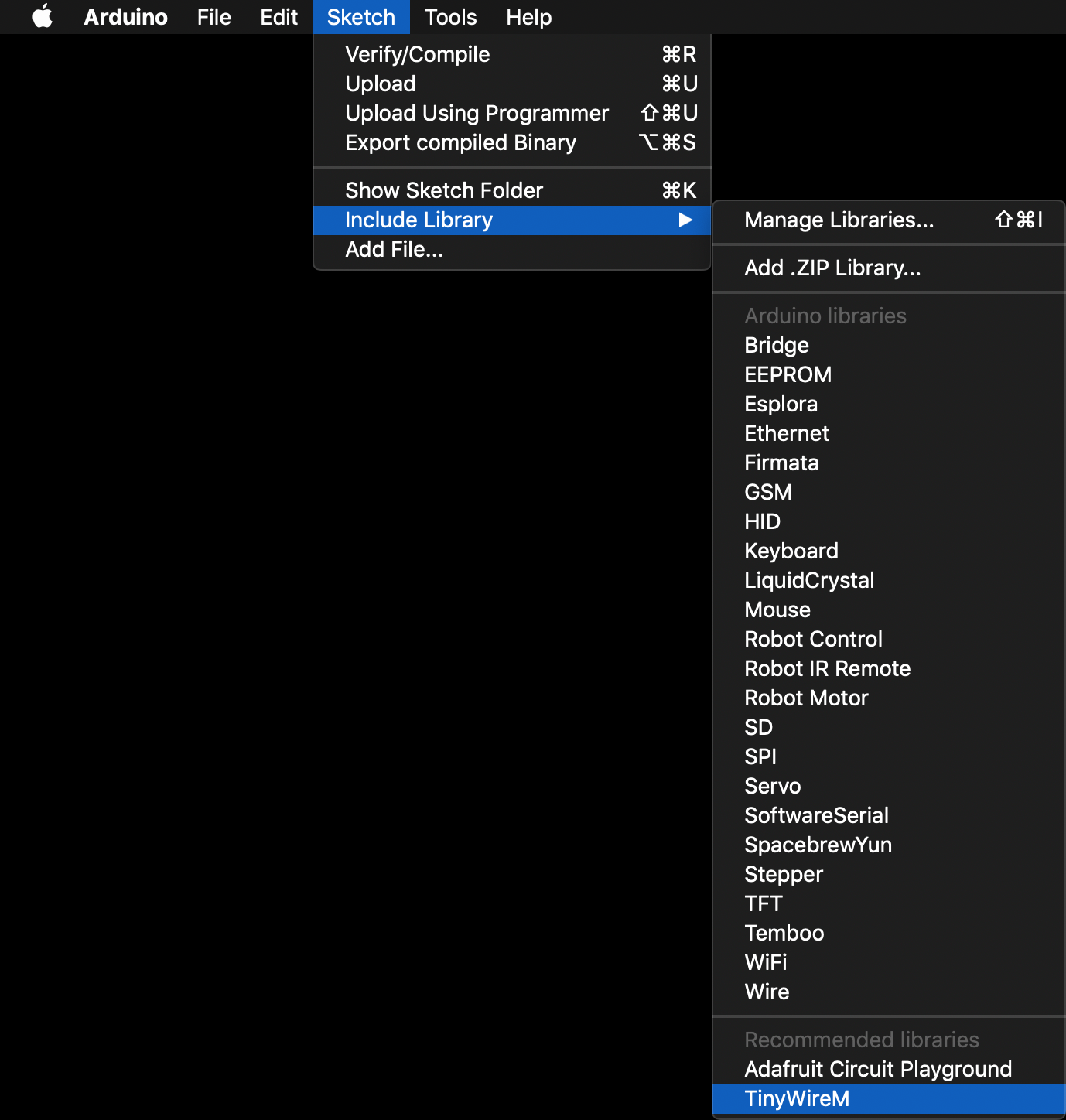
We will also install the TinyWireM Arduino library. This library is necessary to use I2C on ATtiny microcontrollers since the standard Wire library does not work properly on ATtinys.
This module aims to familiarize you with the ATtiny4313 to replace the Arduino UNO that we have been using to prototype.
To learn about AVR microcontrollers in general we direct you to our AVR Microcontrollers tutorial. You will need to follow the sections for ATtinys since we will be using an ATtiny variant in this project. We will be using the Arduino UNO as an ISP as our bootloading device, you may skip any mentions of the Sparkfun Pocket AVR Programmer.
After reviewing the AVR microcontrollers tutorial, you should have the ATtinyCore bootloaders installed, and be familiar with the board settings for ATtinys.
Next, we will introduce the ATtiny4313 and how we will be using it in this project!
We will now cover the ATtiny4313 in detail as it pertains to the Binary CLK. That is, how we will use the ATtiny4313 to replace the Arduino UNO to light up the LEDs that make up the clock.
The benefits of the ATtiny4313 as the microcontroller for our Binary CLK is that it is extremely small and has just the right number of pins to be a perfect fit for the number of LEDs on our clock. We used the Arduino UNO to do our prototyping, and now we need to port our pin mapping and code to the ATtiny4313.
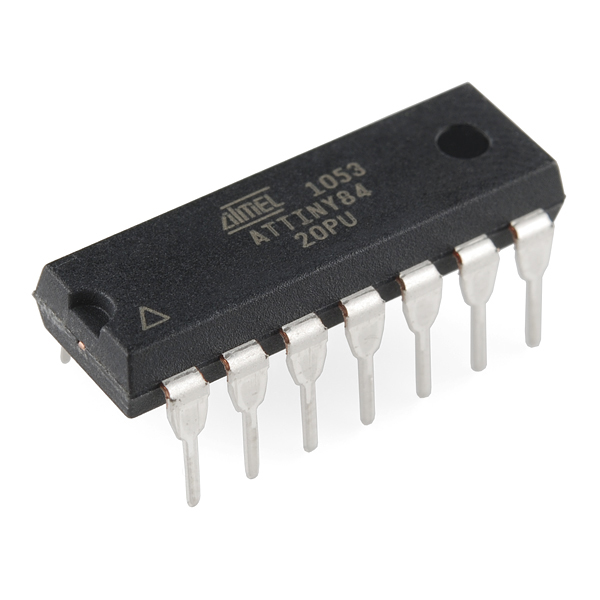
Now we will cover the ATtinyX313 series in general and then how we will use the ATtiny4313 explicitly in the Binary CLK. To learn about the ATTinyX313, we direct you to our ATtinyX313 Microcontroller tutorial. Since we will be using the Arduino UNO as an ISP, you only need to pay attention to the sections pertaining to the Arduino as ISP explicitly to bootload and program the ATtiny4313. We cover the ATtinyX313 through-hole package in the general tutorial; it is also the same package we use in the Binary CLK.
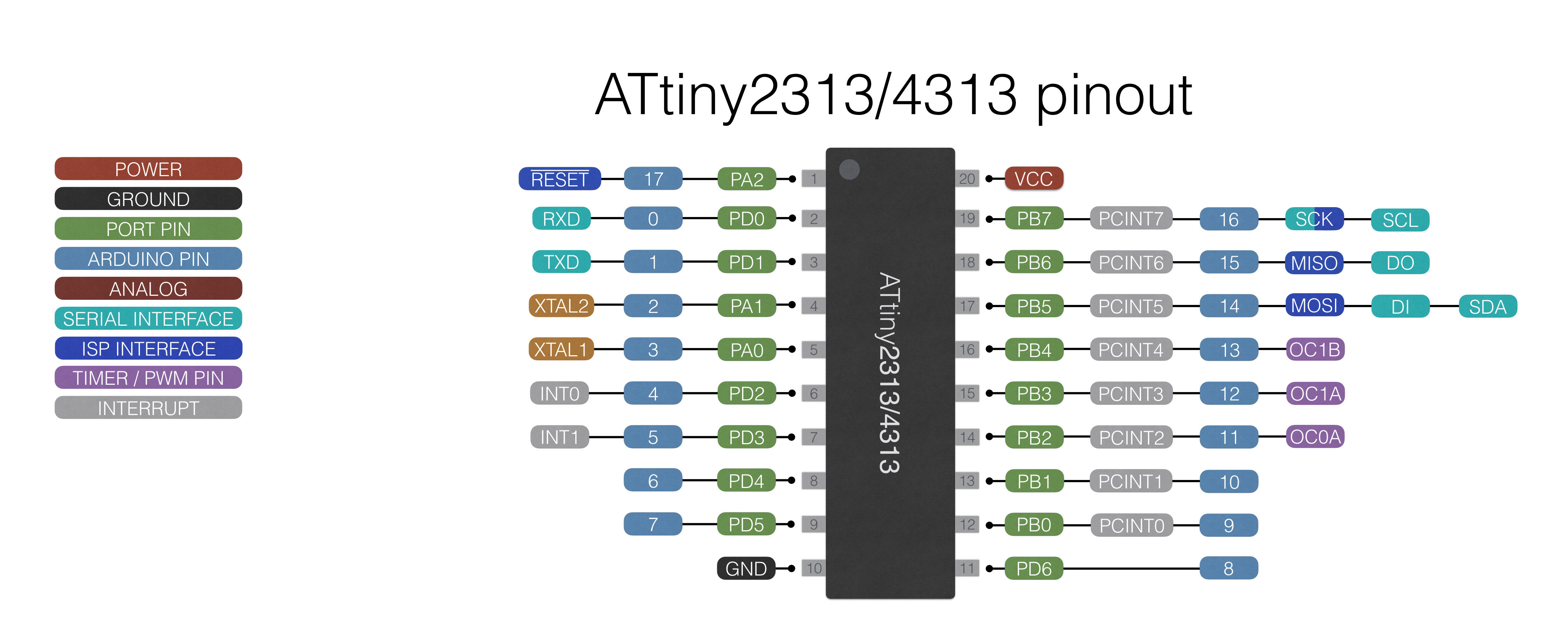
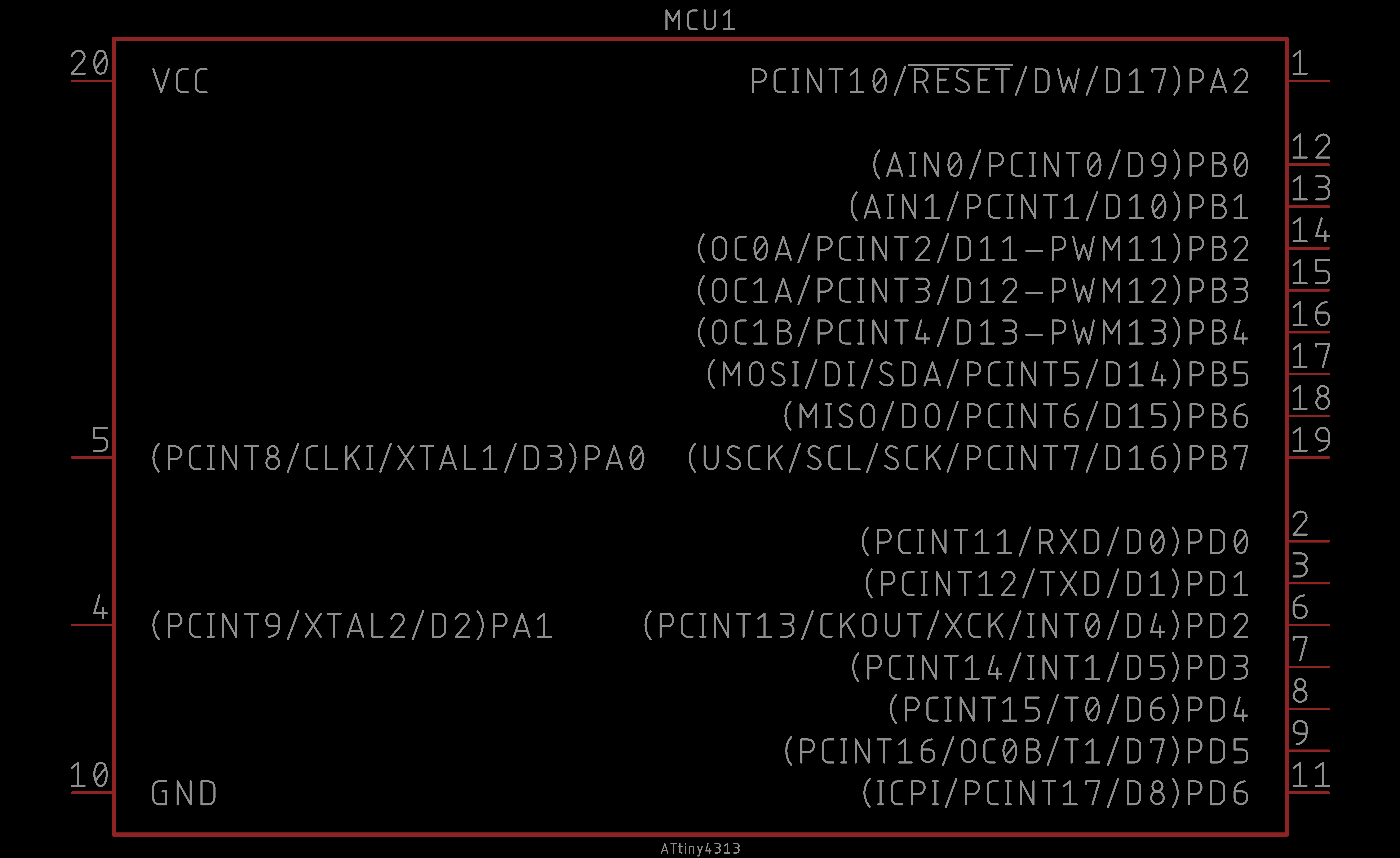
Here we show a reference of the ATtiny4313 pinout:
This pinout describes the physical and logical layout of the ATtiny4313. The physical layout are the physical pins - pins one through eight in a counter-clockwise fashion. The logical layout of the ATtiny84 are the numerous labels tied to each physical pin.
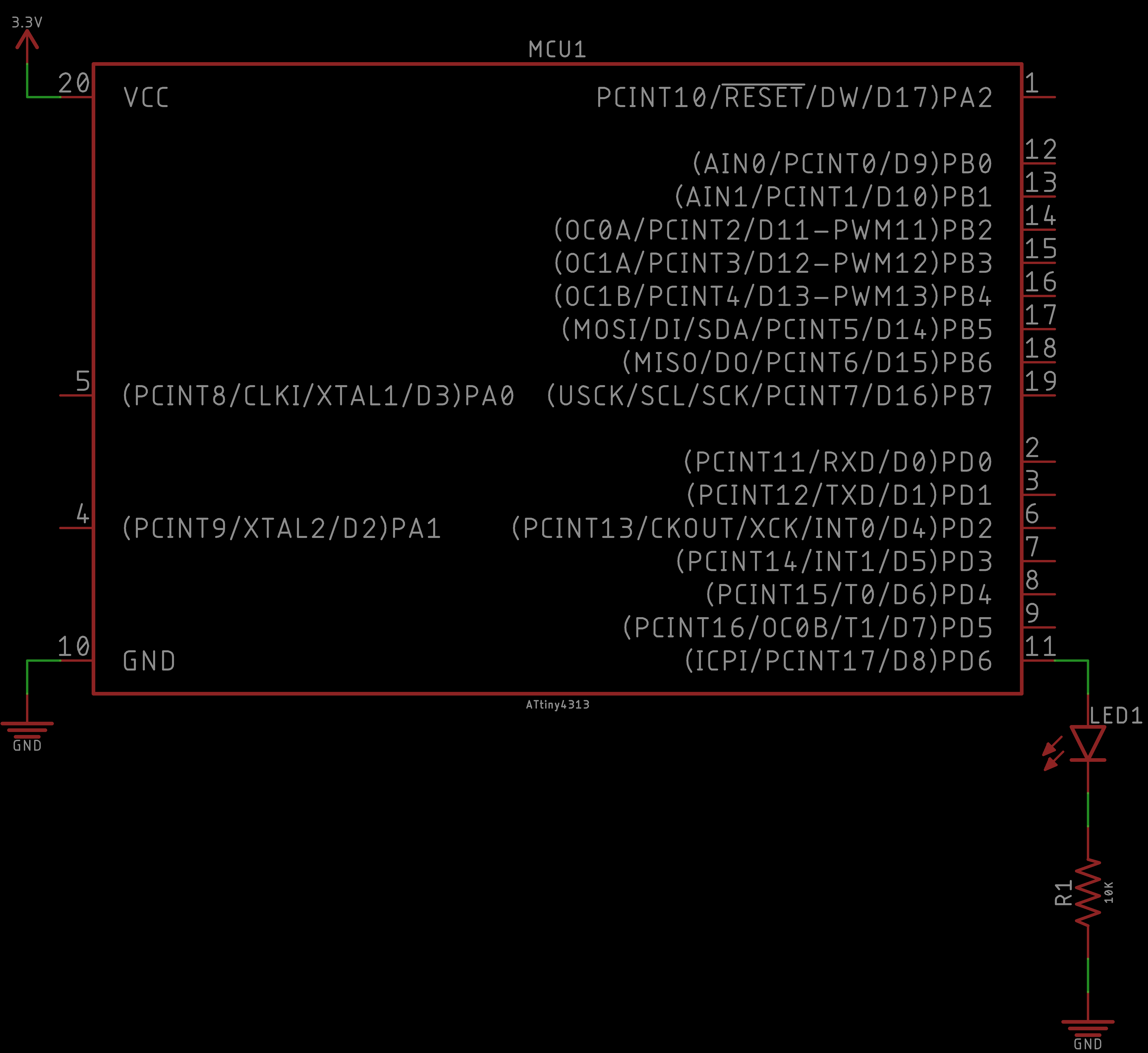
We have the ATtiny4313 device in our EAGLE libraries and it is represented as follows:
Observe the similarities and differences. The numbers represent the physical layout of the ATtiny84. However, the order of these numbers do not match the physical layout of the ATtiny84. The reason is because they are organized logically. On the left, the power connections are shown (i.e. VCC and GND). On the right, the GPIO (general purpose input and output) pins are labeled and ordered by port (e.g. PB = port B).
Each of the GPIO pins have one or more functions. The pins that you can program using the ATtinyCore in the Arduino IDE are labeled on the far right inside the parentheses (e.g. D# for a digital input or output pin, A# for an analog input pin, PWM# for a digital PWM or analog output pin). You would use these pins like you would in any typical Arduino sketch.
In this challenge, we will explicitly program the ATtiny4313. Follow the ATtinyX313 Microcontroller tutorial closely and program the ATtiny4313 to simply blink an LED. We will be using the Arduino UNO as an ISP as our bootloading device, you may skip any mentions of the Sparkfun Pocket AVR Programmer.
Here is the behavior of the challenge simplying blinking an LED:
Note that this solution is NOT the only solution. This is just how we realized it.
The schematic should be similar to the following:
As for the code, we took the Blink example from the Arduino UNO library of examples and modified the pin number to one appropriate on the ATtiny4313:
Again, the results are as follows:
And that is it! Your ATtiny4313 should be blinking an LED. This was a trivial example, but it is the first stepping stone to making more interesting functionality.
Navigate to MrSwirlyEyes' TinyWireM Repository and follow the Introduction to Arduino Installing an Arduino Library tutorial module to install the TinyWireM library into your Arduino IDE.
Confirm you have successfully installed the DS3231 RTC Library:
With the TinyWireM Arduino library installed you will not get a compile error when trying to program the ATtiny4313 while trying to use I2C to communicate with the DS3231.
In the last challenge, we prototyped our Binary CLK using the Arduino UNO; now we will prototype our Binary CLK using the ATtiny4313.
If you have not yet, bootload your ATtiny4313 using the Arduino UNO as an ISP.
Use the same circuit as the last module, except port the pins connected to the Arduino UNO to the ATtiny4313.
To power the ATtiny4313, you can use the 3.3V pin on the Arduino UNO power rail.
We recommend using the same pinout in the last challenge. If you do this, you will not need to change the pin mapping from Arduino UNO to the ATtiny4313. Otherwise, do not forget to map your pins appropriately! It will be difficult to tell whether the RTC is programmed correctly, or you have a logic error since the ATtiny4313 does not have a UART (Serial interface), so you do not have access to helpful debug print statements!
We are bypassing the DS3231 here.
Note that this solution is NOT the only solution. This is just how we realized it. It should look almost exactly the same as the code we started with when testing the single LED. The only difference is the addition of several more LEDs. We also employed an array for its ease, convenience, and code readibilty.
The schematic should be similar to the following:
Again, the code can vary, but here is what we have for our solution for the typical Binary CLK logic code using the DS3231 to get the current time:
Similarly, we have our solution for testing the Binary CLK logic code and looping through every possible time configuration (bypassing the DS3231):
At this point our Binary CLK prototype is complete. All the code on the ATtiny4313 should be correct and after we solder the Binary CLK PCB it should be plug-and-play!
In this module we will solder a replica of the PCB boards we just designed. We will be (optionally) soldering a few SMD components followed by several through-hole components. We will (optionally) use a reflow soldering station for the SMD components, and then a standard soldering iron pen to solder the remainder of the Binary CLK.
Please take your time in this module as soldering is a relaxing and peaceful art. You should only solder when you are relaxed and stress free. Why? Because when you solder there should only be three things present: You, the board, and zen.
The point is, do not rush this and do it right the first time. We always say, the right way to solder is to do it right the first time. It is easy to make mistakes when soldering, but it is much harder to fix any soldering mistakes. Well... as you develop experience, fixing mistakes gets easier, but it very frustrating when you are not comfortable with the process.
If you have never used EAGLE or need a refresher, we have an Introduction to EAGLE PCB Design tutorial that we encourage you to follow. This tutorial will also get you started downloading and installing EAGLE. Furthermore, this will get you equipped with the basics so that you can keep up with the pace of the EAGLE content in this project. In these modules, we proceed slowly, however we are not going to go over the basic tools of EAGLE and assume you have the EAGLE Libraries integrated into the EAGLE environment.
Now we proceed with the PCB designing phase! We will first do the control module. It is a bit more involved and longer. After, we turn to the LED display which is short and simple.
Let us make fun!
We start right off the bat getting into EAGLE and getting the ATtiny4313 onto the schematic.
Next, we add the LED display connector and the DS3231 RTC connections.
Finally, we complete the control module schematic by designing the power system.
Now we hit the board design phase and layout the LED display connector 14-pin header and the 13 resistors.
Next, we layout the remaining components onto the board.
Then, we route the entire board.
Finally, we complete the control module board by adding our texts and labels.
In this last bit we see what the control module looks like in Fusion360 and OSH Park.
This completes the control module PCB. Next, we continue with the LED display PCB.
Here, we start off by designing the LED display schematic.
Next, we turn to the board design and layout the LEDs and 14-pin header.
Finally, we route the board and add our texts and labels.
In this last bit we see what the LED display looks like in Fusion360 and OSH Park.
We have completed the PCB design phase of the Binary CLK project! Next we will solder the PCB board replicas that we just designed.
In this module we will solder a replica of the PCB boards we just designed. We will be (optionally) soldering a few SMD components followed by several through-hole components. We will (optionally) use a reflow soldering station for the SMD components, and then a standard soldering iron pen to solder the remainder of the Binary CLK.
Please take your time in this module as soldering is a relaxing and peaceful art. You should only solder when you are relaxed and stress free. Why? Because when you solder there should only be three things present: You, the board, and zen.
The point is, do not rush this and do it right the first time. We always say, the right way to solder is to do it right the first time. It is easy to make mistakes when soldering, but it is much harder to fix any soldering mistakes. Well... as you develop experience, fixing mistakes gets easier, but it very frustrating when you are not comfortable with the process.
In this first video we remove the artifacts from OSH Park's panelization of our board during the manufacturing process.
Next, we apply solder paste, pick-and-place the SMD components, and reflow the PCB board. It is not required to use the reflowing technique. It is very possible to solder all the SMD component using a standard soldering iron as well.
We proceed to place and solder the resistors.
After, we solder on the LED display connector, 20-pin DIP connector for the ATtiny4313, the header for the DS3231 breakout, and the 9V battery connector. This completes the Binary CLK control module.
We recommend adding some hot-glue or super glue to 9V battery connector where it connects to the PCB board. This wire easily breaks after being bent several times.
Finally we complete LED display by soldering the LEDs and the control module connector. We proceed to assembly the Binary CLK!
We have completed the soldering of the Binary CLK! Now it is ready to complete!
If you have not already, I recommend adding some hot-glue to the 9V battery connector where it is soldered to the PCB board to prevent the wires from breaking.
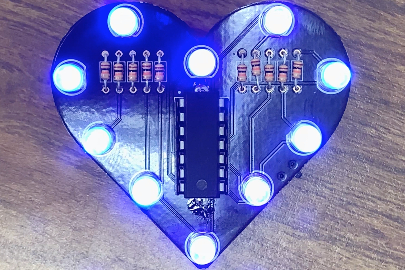
In this module, we complete the Binary CLK.
Technically at this point, you should be able to assemble the LED display and control module, plug the ATtiny4313 into the Binary CLK PCB, insert the DS2331, plug in the 9V battery.
Be gentle when inserting the ATtiny into the DIP connector!
Always use an IC remover when removing the ATtiny!
Flip the switch to turn on your Binary CLK. If you have your code correct and the appropriate pin mapping, then your Binary CLK should function as intended!
If it does not, try to program the ATtiny4313 again. If it still fails to work, check the orientation of the ATtiny4313 on the Binary CLK PCB. Check for shorts, continuity, and voltage across the appropriate points on the PCB.
TODO: GIF or video of Binary CLK working showing appropriate time.
This concludes the Binary CLK! This project is a great example demonstrating the use of the Aruino UNO (or other variant) as a development board. Then we explored options to program an ATtiny microcontroller to perform the same role as the Arduino UNO thus reducing cost, reducing area, and increasing overall efficiency.
We integrated the DS3231 real-time clock module to keep track of time even when our Binary CLK is off. We can always use the DS3231 in another project and have an accurate clock.
We hope this project inspires you to explore ATtiny microcontrollers and/or the DS3231 in your next project!